
Spectrum-X multi-plane setup: make the physical fabric, NIC layout and workload agree
Configure and qualify a Spectrum-X multi-plane deployment with an explicit rail/plane map, a release-matched NIC profile, and per-plane application and failure tests.
A multi-plane fabric can look healthy while a training job uses only one plane. The links may be up, addresses assigned and GPUs visible, but a mismatch between physical wiring, NIC functions, interface names and the application transport leaves much of the intended network idle.
Start with a map that connects those layers. Configure a representative pair of nodes, prove the intended path with a small workload, then add load and a controlled failure test. This is more useful than enabling several attractive features and discovering later that nobody knows which one the job exercised.
The concrete baseline here is NVIDIA Network Operator 26.1.2 and its Spectrum-X RA2.1 NIC configuration. NVIDIA labels that integration technology preview. The constraints below describe that release, not every later Spectrum-X architecture or a general production support guarantee.
Separate a rail, a plane and a host interface
Define these terms in the deployment diagram. A rail describes a grouping in the system’s communication topology. Planes provide parallel fabric connectivity. PCI functions, net devices and RDMA devices are host-visible objects that must map to the intended physical connectivity.
Give each connection a row containing node, GPU locality, physical NIC, PCI function, switch port, rail, plane, net-device name, RDMA-device name and addressing. Keep the current discovered mapping beside the desired one. A renamed interface does not change which cable it reaches.
A two-plane illustrative map might assign the first function of each relevant NIC to plane A and a second function to plane B. That mapping is an example to validate against the selected hardware mode, not a rule for every NIC layout. Hardware and software plane handling can expose different device arrangements.
Record which components the planes share. Parallel planes do not establish independent power, PCIe or switch-failure domains merely because their names differ.
Choose one supported reference-architecture combination
The 26.1.2 Spectrum-X guide defines the RA2.1 fields. In that baseline, swplb supports software packet load balancing on the documented ConnectX-8 and BlueField-3 SuperNIC devices; hwplb is restricted to ConnectX-8. Two or four planes are described for those load-balancing modes. uniplane treats each port as a separate plane without plane-level load balancing in this version.
Do not combine a mode name from a newer guide with the older CRD. Check the installed schema and supported device IDs before submitting configuration. A rejected combination is useful validation, while an accepted object still needs reconciliation and workload evidence.
An abbreviated canary template is:
apiVersion: configuration.net.nvidia.com/v1alpha1
kind: NicConfigurationTemplate
metadata:
  name: spectrumx-canary
  namespace: nvidia-network-operator
spec:
  nodeSelector:
    example.com/spectrumx-canary: "true"
  nicSelector:
    nicType: "1023"
  template:
    numVfs: 1
    linkType: Ethernet
    spectrumXOptimized:
      enabled: true
      version: RA2.1
      overlay: none
      multiplaneMode: hwplb
      numberOfPlanes: 2
The selector is deliberately narrow and illustrative. It must identify only qualified maintenance nodes. This is not a complete fabric deployment: switch profiles, addressing, firmware sources, operator prerequisites and workload networks remain part of the release configuration.
Establish configuration ownership and the release manifest
Pin the operator, NIC Configuration Operator, DOCA components, driver, firmware and switch software to a supported combination. Retain immutable image or package identities rather than the word latest. Use the validated Spectrum-X stack to locate the applicable combination, then preserve the dated row used for the deployment.
Choose one owner for each configuration family. An operator continuously reconciling NIC settings and a boot script applying different settings create a moving target. The same applies when a manual reset restores defaults that a service later replaces.
Read the NIC configuration rules before combining optimizations. Spectrum-X configuration in this baseline is not an invitation to stack roceOptimized and arbitrary raw NVConfig on top. Record which settings are persistent and which must be restored after boot.
For RA2.1, the cited operator includes the SPC-X congestion-control package in its image. Earlier RA profiles have a different provisioning path. Keep that package decision alongside the firmware source and template, rather than adding an unrelated service installation to an already managed node.
Make addressing and naming reproducible
Allocate distinct, documented addresses for the intended secondary interfaces and planes. Reserve the management and ordinary pod network for their own roles. Record routes and neighbor resolution for each selected path; an address on an interface does not prove that traffic to the peer uses it.
When using the documented interface-name templates, retain the PCI-to-rail mapping and the generated names in the release evidence. Validate after provisioning and reboot. Automation should discover and check identities rather than assume yesterday’s enumeration order survives every hardware change.
Do not use a broad network-policy assumption to infer isolation on secondary networks. Review what the chosen CNI and host configuration actually enforce on those paths. The ordinary pod network’s controls may not cover every attached interface.
Admit a canary only after each layer passes
Begin with read-only observations in the configured management context:
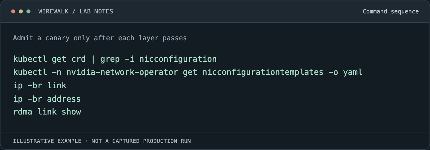
Read and copy the example as text
kubectl get crd | grep -i nicconfiguration
kubectl -n nvidia-network-operator get nicconfigurationtemplates -o yaml
ip -br link
ip -br address
rdma link show
Inspect the per-device reconciliation objects and events discovered through the installed API. A desired template is not a readback of effective firmware or runtime state. Check the running driver, actual link configuration and the state after any required activation event.
Test one host pair, then one GPU communication pair using the qualified application stack. Record interface and device selection, peer placement, message size and input. A successful IP ping does not establish RDMA or GPU-memory communication.
Measure plane use under the workload that matters
Collect counter deltas per plane over the same interval as the application. Include transmitted bytes, errors, congestion signals and relevant retransmission observations. Save reset or collector-restart events so rate calculations do not turn discontinuities into traffic.
Use a representative collective or distributed training segment and compare its step-time distribution with the quiet baseline. Equal traffic on every link is not a universal acceptance rule: selection mode, topology and workload can legitimately produce unequal use. The evidence must explain the observed distribution and show that intended capacity is reachable.
If one plane remains idle, inspect the application transport selection, device exposure, addressing and route map before changing congestion parameters. If every plane is active but tails worsen with load, continue with ECN and SPC-X parameter diagnosis.
Test loss and restoration with an explicit service contract
Define which maintenance event the design should tolerate and what temporary performance change is acceptable. Use isolated canary resources and a supported recovery procedure. Preserve checkpoints or other recoverable application state before the experiment.
Observe the application’s progress, plane state transitions and restored traffic after recovery. A process remaining alive while making no progress is not a successful resilience test. Nor should a planned bandwidth reduction be mislabeled a complete failure if it fits the agreed operating contract.
Keep the final map, profile, applied-state evidence and workload results as a release unit. The Kubernetes multi-rail RDMA guide extends this process into the pod boundary, where devices and networks must be allocated together.