
Sample GPU, rail and storage topology map
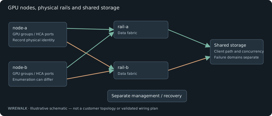
A simplified illustrative GPU cluster topology with separate management, data rails and shared storage, plus the identity fields required for a real handover.
A diagram is a navigation aid, not a wiring record
The diagram below is fictional and deliberately simplified. It shows two GPU nodes, two data rails, shared storage and a separate management path. It does not imply a validated reference architecture, specific switch capacity or independent storage failure domains.
Connect the drawing to an identity table
| Record | Fields to retain privately |
|---|---|
| GPU | Node, device identity, PCI BDF, local topology and allocation mapping |
| NIC/HCA | Physical identity, PCI BDF, port, firmware and OS device name |
| Fabric | Physical rail/plane, switch and port, supported link rate/width and routing owner |
| Storage | Client path, storage endpoint/failure domain and relevant filesystem role |
| Management | Recovery access, access owner and dependencies, separate from workload traffic |
Public copies should remove operational addresses, unique identifiers, customer names and sensitive management details. A real handover retains those in the agreed private evidence channel.
Validate the map
Check the live host inventory against cabling and switch state, then observe the workload on the intended paths. A line drawn between a GPU and a NIC does not establish supported GPU peer access, GPUDirect RDMA or useful bandwidth.
Record a revision, configuration owner and the event that requires rediscovery: a replacement card, changed firmware, reimage or cabling change. The rail-matching scenario shows why the OS enumeration alone is not a durable physical map.